
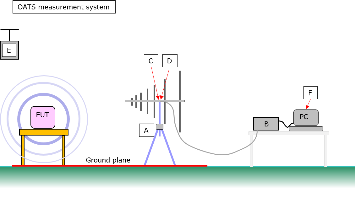
Equipment required:
A RF200 Antenna + stand
B SA1002 EMC analyser
C SA1020 pre-amplifier
D RF700 30MHz HP filter
E ERS Reference source
F Software for your PC
Note:
For 3GHz system, add RF230 antenna and change EMC analyser to SA3000
Practical notes:
The standards require use of a site free of reflections, a ground plane and height scanning of the antenna. Limited resources dictate that these requirements generally cannot be achieved. The ERS avoids the gross measurement uncertainties that would result.
In addition, ambient noise will mask EUT emissions. Laplace software includes a feature to cancel out the ambient noise so that EUT emissions can be identified and measured.
RF Emissions (Cell/Chamber)
LC300/2
Typical arrangement for emissions measurement in LC300/2
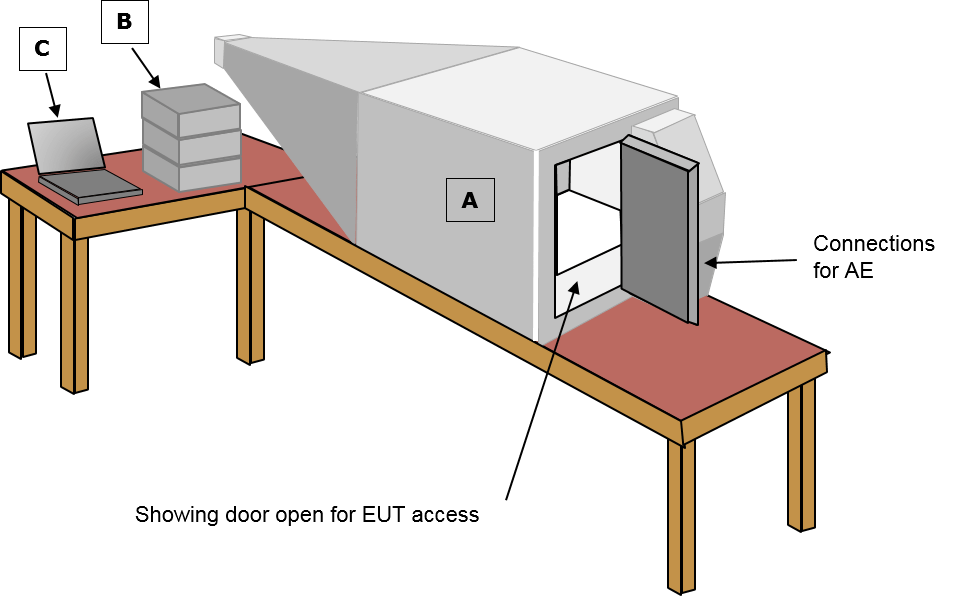 Equipment required:
A LC300/2 Test cell
B SA1002 EMC analyser
C Software for your PC
Note:
For 3GHz system, change EMC analyser to SA3000.
The LC300 accepts products up to 30 x 30 x 30cm.
Filters for I/O feeds to the EUT can be fitted to suit customer requirements (eg, USB, Ethernet, Power, RS232, RF feeds, etc…)
LC600
Typical arrangement for emissions measurement in LC600
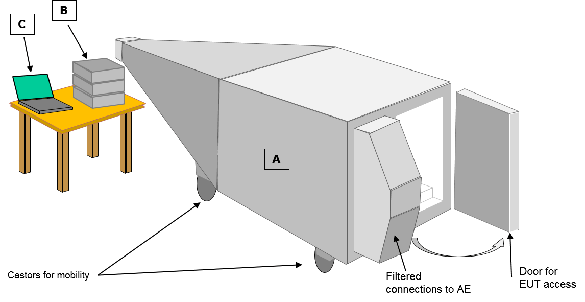
Equipment required:
A LC600 Test cell
B SA1002 EMC analyser
C Software for your PC
Note:
For 3GHz system, change EMC analyser to SA3000
The LC600 accepts products up to 60 x 60 x 60cm.
Filters for I/O feeds to the EUT can be fitted to suit customer requirements (eg, USB, Ethernet, Power, RS232, RF feeds, etc…)
Chamber emissions measurement system
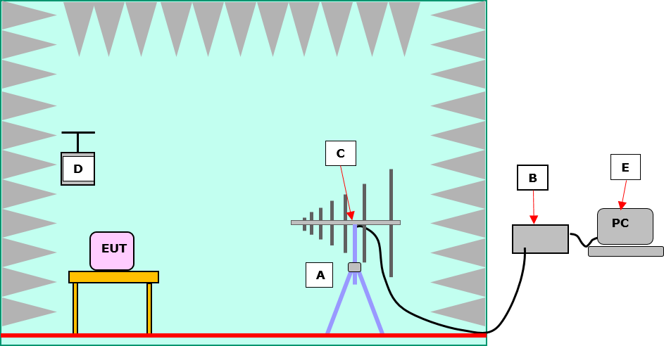
Equipment required:
A RF200 Antenna + stand
B SA1002 EMC analyser
C SA1020 pre-amplifier
D ERS Reference source
E Software for your PC
Note:
Contact Laplace for discussions regarding the chamber.
For 3GHz system, add RF230 antenna and change EMC analyser to SA3000
Practical notes:
Ambient noise will be essentially eliminated. However, chamber characteristics may introduce uncertainties which can be corrected by use of the ERS. Diagram shows SAC (Semi Anechoic Chamber) with reflective floor to emulate OATS. FAC (Fully Anechoic Chamber) has RF absorber on the floor. This avoids the requirement for height scanning of the antenna.