LC300/2
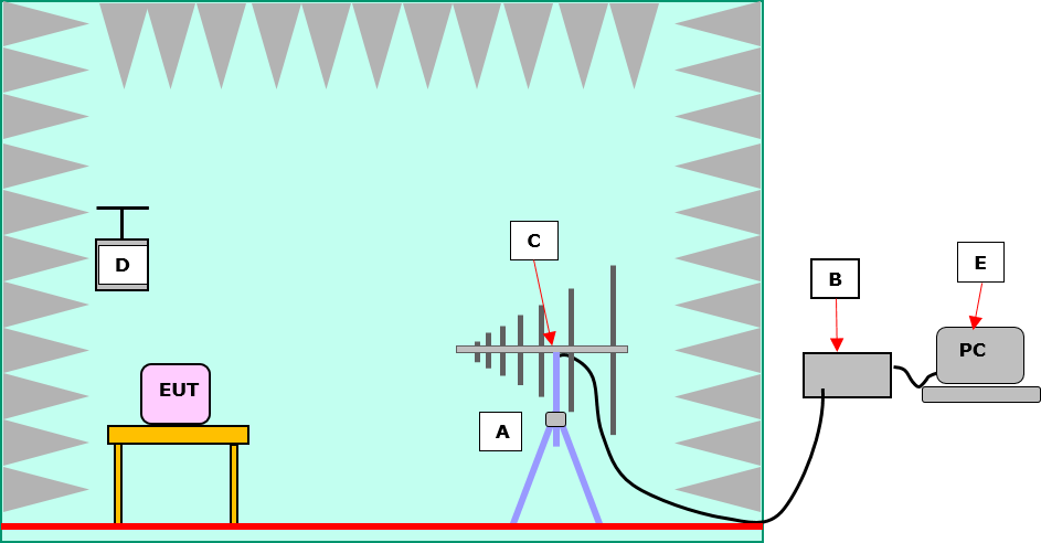
Typical arrangement for emissions measurement in LC300/2
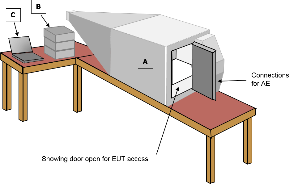 Equipment required:
A LC300/2 Test cell
B SA1002 EMC analyser
C Software for your PC
Note:
For 3GHz system, change EMC analyser to SA3000.
The LC300 accepts products up to 30 x 30 x 30cm.
Filters for I/O feeds to the EUT can be fitted to suit customer requirements (eg, USB, Ethernet, Power, RS232, RF feeds, etc…)
LC600
Typical arrangement for emissions measurement in LC600
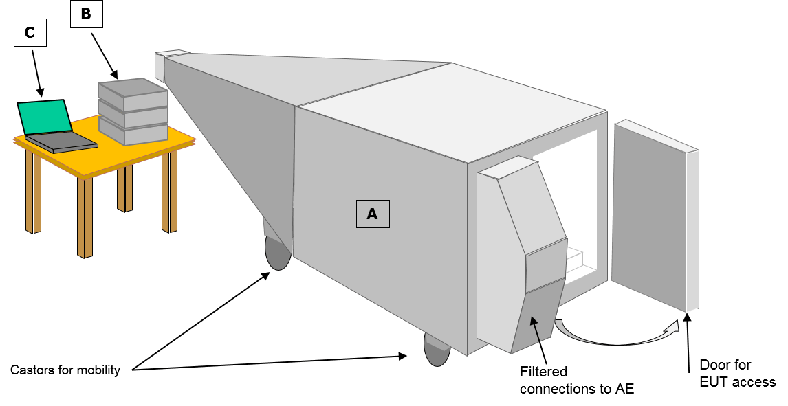
Equipment required:
A LC600 Test cell
B SA1002 EMC analyser
C Software for your PC
Note:
For 3GHz system, change EMC analyser to SA3000
The LC600 accepts products up to 60 x 60 x 60cm.
Filters for I/O feeds to the EUT can be fitted to suit customer requirements (eg, USB, Ethernet, Power, RS232, RF feeds, etc…)