
Conducted immunity tests are divided into 2 groups:
- RF tests (conducted RF to IEC61000-4-6)
- Others: covering ESD, transients, bursts, dips and interruptions.
- IEC61000-4-2 ESD
- IEC61000-4-4 EFT/BURST
- IEC61000-4-5 SURGE
- IEC61000-4-8 MAGNETIC FIELD (POWER FREQUENCY)
- IEC61000-4-9 MAGNETIC FIELD (PULSED)
- IEC61000-4-11 DIPS AND INTERUPTS
Laplace offers cost effective and compliant solutions for all above.
RF Tests
IEC61000-4-6 conducted immunity test systems require two elements… the main part (common to all systems) comprising the signal generation, amplification, control and software elements, and the other part being the injection devices which must be matched to the EUT cables.
There are two possible modes of operation:
Conventional Mode: The IEC61000-4-6 standard requires that the calibration of the input RF signal is achieved using a preliminary sweep with a calibration adaptor (150ohm to 50ohm). The power settings are recorded and the same settings are then used when the ‘real’ test is commenced.
Enhanced Mode: The Signal injected into the cable is measured and provides feedback to the system controller thus providing closed loop control. Whilst not following the standard exactly, it does provide complete assurance that the applied signal is precisely at the level specified, and provides other benefits too. (see Technical Paper)
Each kit (or system) is complete with:
- signal generator (synthesiser)
- modulation
- power amplifier
- level control system
- Windows compatible software for your PC
- USB interface
- EUT monitoring facilities
- all cables and connectors
The preferred injection method is via the appropriate CDN(s). These are the devices that are connected to the EUT cables. They couple the RF into the cables. CDNs are the preferred technique according to the IEC61000-4-6 standard. We have a comprehensive range of CDNs to cover all standard cable types. Other injection devices may be used – see below.
Conventional CDNs:
The conventional CDNs are each matched to suit a particular cable type
Versatile CDNs:
These versatile CDNs include adaptors such that one CDN can cover several cable types, thus achieving a significant cost saving.
Enhanced CDNs:
The enhanced CDNs have an RF Signal monitoring system so that the injected RF level can be monitored by the control unit and used as a feedback signal to control the applied level
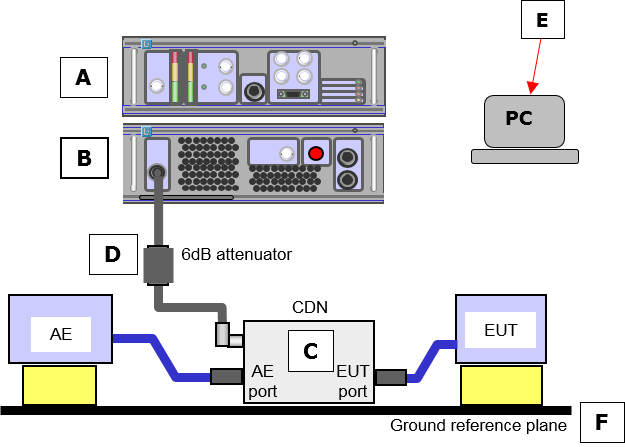
Below shows the setup for a typical conducted RF immunity test facility acc. IEC61000-4-6 using CDNs for injection. (preferred method).
All CDNs are versatile and can be configured for a variety of cable types.
Note that every cable normally connected to the EUT must be connected via CDNs during testing.
Alternative injection devices such as EM clamps and Bulk Current Injection clamps (BCI) are also available. Note that these are less efficient than CDNs and will therefore require higher RF input power to achieve a given stress level on the EUT cable.
Power required according to IEC61000-4-6 (Appendix E)
| Injection device | Required power for 10V stress on cable |
| CDN | 7w |
| BCI | 176w |
| EM clamp | 28w |
These figures allow for the 6dB attenuator and the 80% amplitude modulation requirement.
Equipment required:
A RFIC-4-6 Synthesiser
B RF0250 Power amplifier
C S46xxx CDN to suit cable*
D Att-6/20 6dB attenuator
E Software for your PC
F 46GP Ground plane
Note:
Calibration fixtures type 46ZZ required for conventional operation.
* E46xxx series provides enhanced (closed loop) control of applied stress level